Add to Cart
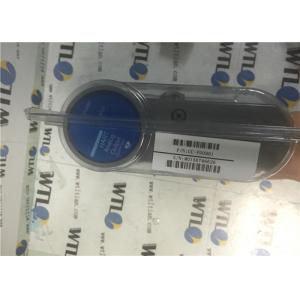
Digital Output 24V Redundant Power Supply Module CC-PDOB01 51405043-175 FW G HW G
QUICK DETAILS
DESCRIPTION
SEPCIFICATIONS
| Parameter | Specification |
| Input / Output Model | CC-PDOB01 – 24Volt Digital Output , Field Isolated, Bussed output |
| IOTA Models | CU-PDOB01 – 24Volt Digital Output , Field Isolated, Bussed output |
| Output Channels | 32 |
| Load Voltage | 30 VDC Maximum |
| Galvanic Isolation | 1500 VAC RMS or ±1500 VDC |
| On-State Voltage | 24 V (typ), load current @ 0.5A |
| Off-State Voltage | 0v VDC (max) (3.3VDC (max) indicated under no-load condition) |
| Off-State Leak Current | 0.5 μA (max) |
| Turn-On/Turn-Off Time | 10 ms (max) |
Relay Digital Output (32 pt):
Digital output with NO or NC dry contacts. Can be used for low power or high power applications.
Maximum Steady State Load Currentper Output
Current → Voltage
3 A → 250 VAC (resistive)
3 A → 125Maximum Steady State Load Currentper Output VAC (resistive)
3 A → 30 VDC (resistive)
1 A → 48 VDC (resistive)
0.2 A → 125 VDC (resistive)
2 A → 250 VAC (Inductive – 0.4 power factor)
2 A → 125 VAC (Inductive – 0.4 power factor)
1 A → 30 VAC (Inductive L/R = 100 ms)
0.3 A → 48 VAC (Inductive L/R = 100 ms)
0.1 A → 125 VAC (Inductive L/R = 100 ms)
Contact Life
Operations → % of Max. Load
10,000,000 → (Mechanical Life)
200,000 @ 3 A (100%)
120Ώ + 0.03°F for each channel
Digital Output Bussed 24 VDC (32 pt):
The Digital Output bussed 24VDC module provides reliable 24V digital output signals to control other processes. The DO24V can support high energy outputs to reduce the number of external components in the output loop.
| Parameter | Specification | |||||||
| Input / Output Model | CC-PDOB01 – 24Volt Digital Output , Field Isolated, Bussed output | |||||||
| CU-PDOB01 – 24Volt Digital Output , Field Isolated, Bussed output | ||||||||
| IOTA Models | CC-TDOB11 | Non Redundant | 6” | |||||
| CU-TDOB11 | Redundant | 12” | ||||||
| Output Channels | 32 | |||||||
| Load Voltage | 30 VDC Maximum | |||||||
| Load Current | Per Channel | Per 8 Channels | Per Module | |||||
| (A group of 8 channels consists of | One Short Condition | (1) | 0.5A | 3A | 6A | |||
| channels: 1-8, 9-16, 17-24, and 25-32) | ||||||||
| (1) | ||||||||
| Two Short Condition | 0.5A | 1.5A | 6A | |||||
| Galvanic Isolation | 1500 VAC RMS or ±1500 | VDC | ||||||
| On-State Voltage | 24 V (typ), load current @ 0.5A | |||||||
| Off-State Voltage | 0v VDC (max) (3.3VDC (max) indicated under no-load condition) | |||||||
| Off-State Leak Current | 0.5 μA (max) | |||||||
| Turn-On/Turn-Off Time | 10 ms (max) | |||||||
| Gap (0 current) of Output to Field on | 10 ms maximum (applies to Redundancy only) | |||||||
| Switchover | ||||||||
| (1) | ||||||||
One / Two Short Condition parameter denotes the maximum current that can be passed through the DO with the short condition indicated before the short protection mechanism disables the function. As an example, the DO can drive a maximum of 1.5A per 8 channels with two channels shorted before the short protection mechanism will disable all 8 channels affected.

OTHER SUPERIOR PRODUCTS
